SERIES FIVE
Assembly Instructions
WIRE STRIPPING
1. Strip wire to required length. (See Figure at right). When using hot wire stripping, do not wipe melted insulation material on wire strands; with mechanical strippers do not cut or nick strands.
2. See Table 1 for proper finished outside wire dimensions.
3. Twist strands together to form a firm bundle.
4. Insert stripped wire into contact applying slight pressure until wire insulation butts against wire well. Check inspection hole to see that wire strands are visible. If there are strayed wire strands, entire wire end should be re-twisted.
Stripping Dimensions

When wire is stripped and properly installed into contact, the next step is to crimp the wire inside the contact by using the proper crimping tool.
| Wire Size | A |
| 22. 22M, 22D | .125 (3.18) |
| 20 | .188 (4.77) |
| 16 | 188 (4.77) |
| 12 | 188 (4.77) |
| Contact Size | Wire Dimension (inches)** | |
| Min. | Max. | |
| 10 | .135 | .162 |
| 12 | .097 | .142 |
| 16 | .065 | .109 |
| 20 | .040 | .077 |
| 22 | .034 | .060 |
| 22M, 22D | .030 | .050 |
CRIMPING
See table on preceding page for recommended M22520 series crimping tools, turret head or positioner selection settings according to contact size, part number and wire gauge size.
1. Insert stripped wire into contact crimp pot. Wire must be visible through inspection hole.
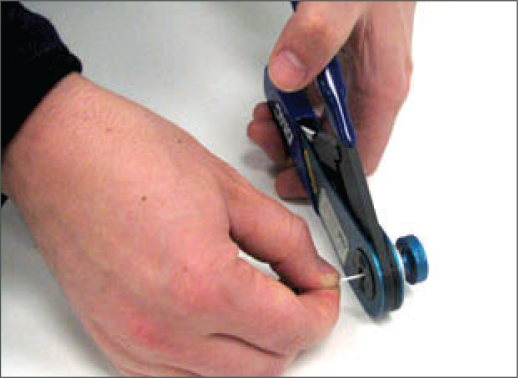
2. Using correct crimp tool and locator, cycle the tool once to be sure the indentors are open, insert contact and wire into locator. Squeeze tool handles firmly and completely to insure a proper crimp. The tool will not release unless the crimp indentors in the tool head have been fully actuated.
3. Release crimped contact and wire from tool. Be certain the wire is visible through inspection hole in contact.

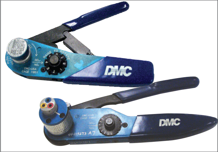
Examples of M22520 Series Crimping Tools: Shown top: tool used for small size 22, 22D
and 22M contacts.
Shown bottom: tool used for size 20, 16 or 12 contacts and has a positioner that can be dialed for each contact size.
Contact Insertion
| Descriptions | Images |
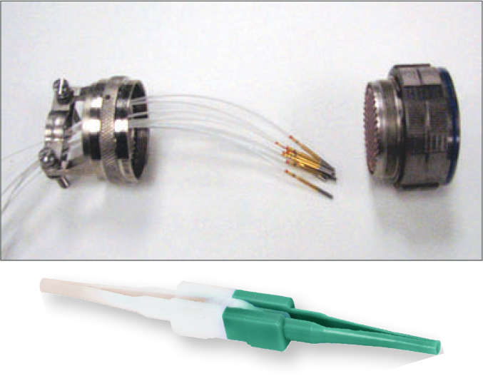
| 1. First remove hardware from the plug and receptacle and slide the hardware over wires in proper sequence. |
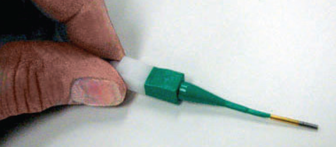
Note: All plastic tools are double-ended. The colored side is the insertion tool and the white side is the removal tool. |
| 2. Use proper plastic or metal insertion tool for corresponding contact. (Consult Insertion Tool table on preceding page 8). Slide correct tool (with plastic tool use colored end) over wire insulation and slide forward until tool bottoms against rear contact shoulder. |
Plastic tool with contact in proper position.
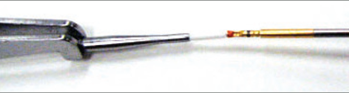
Metal tool with contact. |
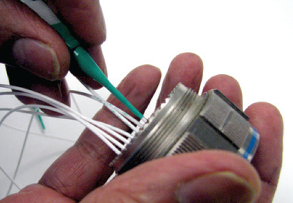
| 3. Next align the tool and contact up to the properly identified cavity at rear of connector plug. Use firm, even pressure; do not use excessive pressure. It is recommended to start at the center cavity. Contact must be aligned with grommet hole and not inserted at an angle. Push forward until contact is felt to snap into position within insert. | 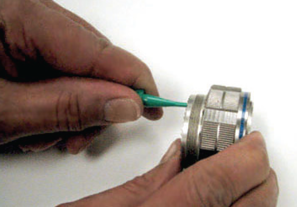 |
| 4. Remove tool and pull back lightly on wire, making sure contact stays properly seated and isn’t dragged back with the tool. Repeat operation with remainder of contacts to be inserted, beginning with the center cavity and working outward in alternating rows. |
CAUTION: when inserting or removing contacts, do not spread or rotate tool tips. |
|
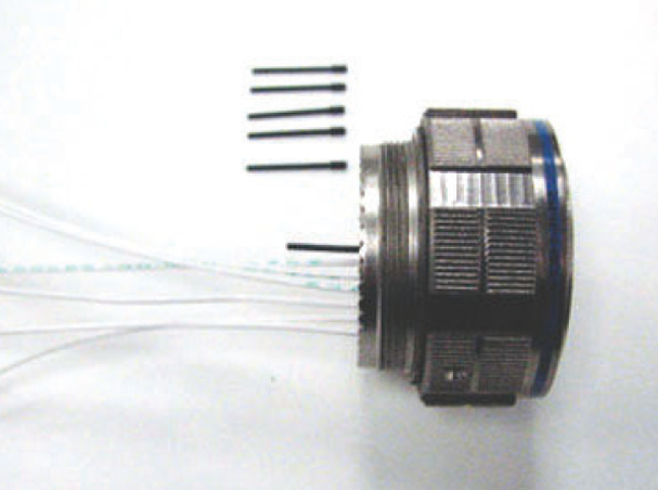
5. After all contacts are inserted, fill any empty cavities with wire sealing plugs.(Refer to sealingplug charts page 8) |
 |
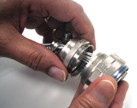
| 6. Reassemble plug or receptacle hardware slide forward and tighten using connector pliers. Connector holding tools are recommended while tightening back accessories. When using strain relief, center wires at bar clamp. Slide clamp grommet into position and tighten clamp bar screws. When tightening screws, pressure should be applied in the same direction that clamp is threaded to rear threads of connector. When not using clamp grommet, build up wire bundle with vinyl tape so clamp bar will maintain pressure on wires. | 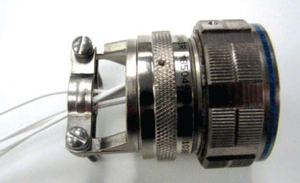 |
CONTACT REMOVAL
| Descriptions | Images |
| 1. Remove hardware from plug or receptacle and slide hardware back along wire bundle. |
 |
| 2. Use proper plastic or metal removal tool for corresponding contact. (Consult Removal Tool table on page 8). Slide correct size tool over wire insulation. |
Use white end of plastic tool fo removal of contacts. |
|
3. Insert plastic or metal removal tool into contact cavity until tool tips enter rear grommet and come to a positive stop. Hold tool tip firmly against positive stop on contact shoulder. Grip wire and simultaneously remove tool and contact. (On occasion, it may be necessary to remove tool, rotate 90° and reinsert.) |
Removal of contacts with metal tool. |
SERIES FIVE MINI-BAND TERMINATION
Mini-band Termination: For assembling cables to overmolded style S5 connectors or backshells, the Mini-band system offers quick termination of cable shields and flexibility to be utilized on a wide range of parts with just one band size. These rugged straps have passed numerous hazadous environmental testing. Including shock and vibration. Approved for use in military and aerospace applications.
MATERIALS:
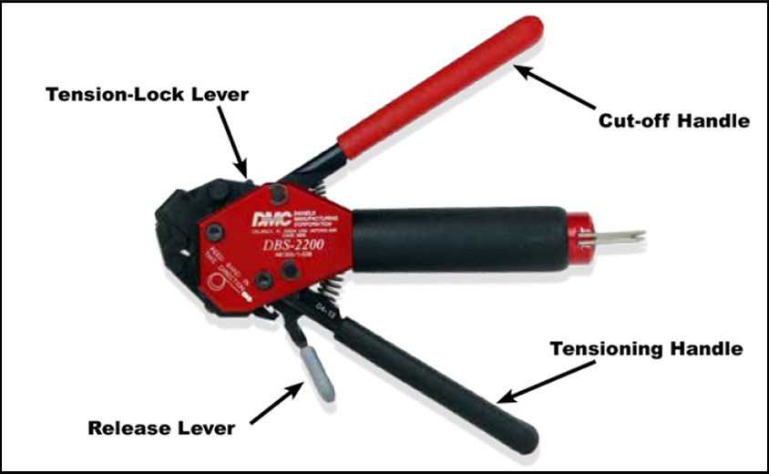
Mini-band installation tool. Use with .120” (3.05 mm) wide bands, 6.75 inches (172 mm.) length, 1.2 pounds (0.6 Kg.)
Mini-band, .120” (3.05 mm) wide. Available in two lengths, flat or pre-coiled. Stainless steel.
| Description | DMC Part Number | Military Part Number |
| Mini-Band Installation Tool | DBS-2200 | M81306/1B |
| Length | Accommodates Diameter | DMC Part Number | Military Part Number | ||
| Inches | mm | Inches | mm | ||
| 8.125 | 206.38 | .88 | 22.35 | DBS-1287 | M85049/128-7 |
| Steps |
Descriptions
|
| Step 1: Prepare the Connector and Cable Braid | Prepare the connector and cable braid for band termination process (see DMC Website). |
| Step 2: Prepare Band | Using an appropriate size band, feed the end of the band through the narrow slot on the buckle twice. This will create a double-looped band. Never use a single-looped band. To hasten the termination process on smaller adapters, pull on the end of the band to reduce the diameter of the loop |
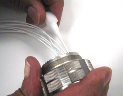
| Step 3: Insert Looped Band into Tool | Squeeze the release lever and insert the end of the band into the nose of the tool. Ensure the orientation of the band matches the graphic on the body of the tool (coil down when the tool is held upright) |
| Step 4: Positioning | Position the connector and the shield assembly through the band |
|
Step 5: Tighten Band around Braid/Connector
|
Repeatedly squeeze the tensioning handle until the band closes around the assembly. Once the band is closed around the assembly, use half strokes of the handle until the band is tight against the braided cable. Release the tensioning handle and allow it to open fully. With one final stroke, close the tensioning handle until it locks against the tool body. This indicates that the band has been tightened to the pre-set tension. |
|
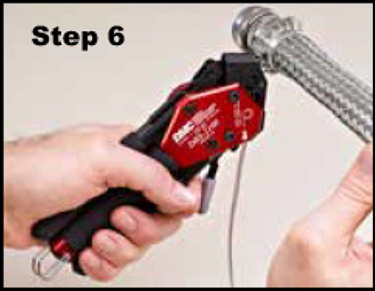
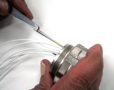
Step 6: Cut Off
|
Once the tensioning handle is locked in place, squeeze the cut-off handle to finish the termination process. Both handles will open up on their own. (If shrinkable tubing is to be applied, it is recommended that the band is wrapped in tape and the excess braid folded back over the band to prevent cutting of shrinkable tubing). |
|
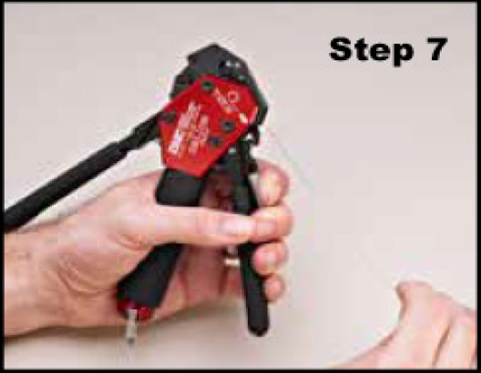
Step 7: Remove Excess Band Material
|
Release the tensioning handle and then squeeze the release lever. While squeezing the release lever, carefully pull on the band and slide it out of the tool and discard. |