
Login
You must first login to download drawings/models.
Incorrect username or password.
You must first login to download drawings/models or register for webinars.
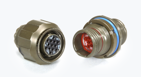
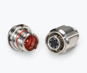
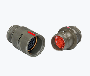
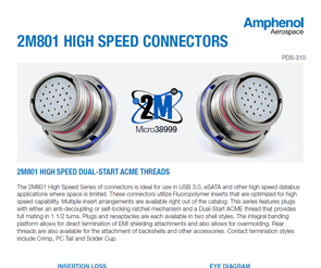
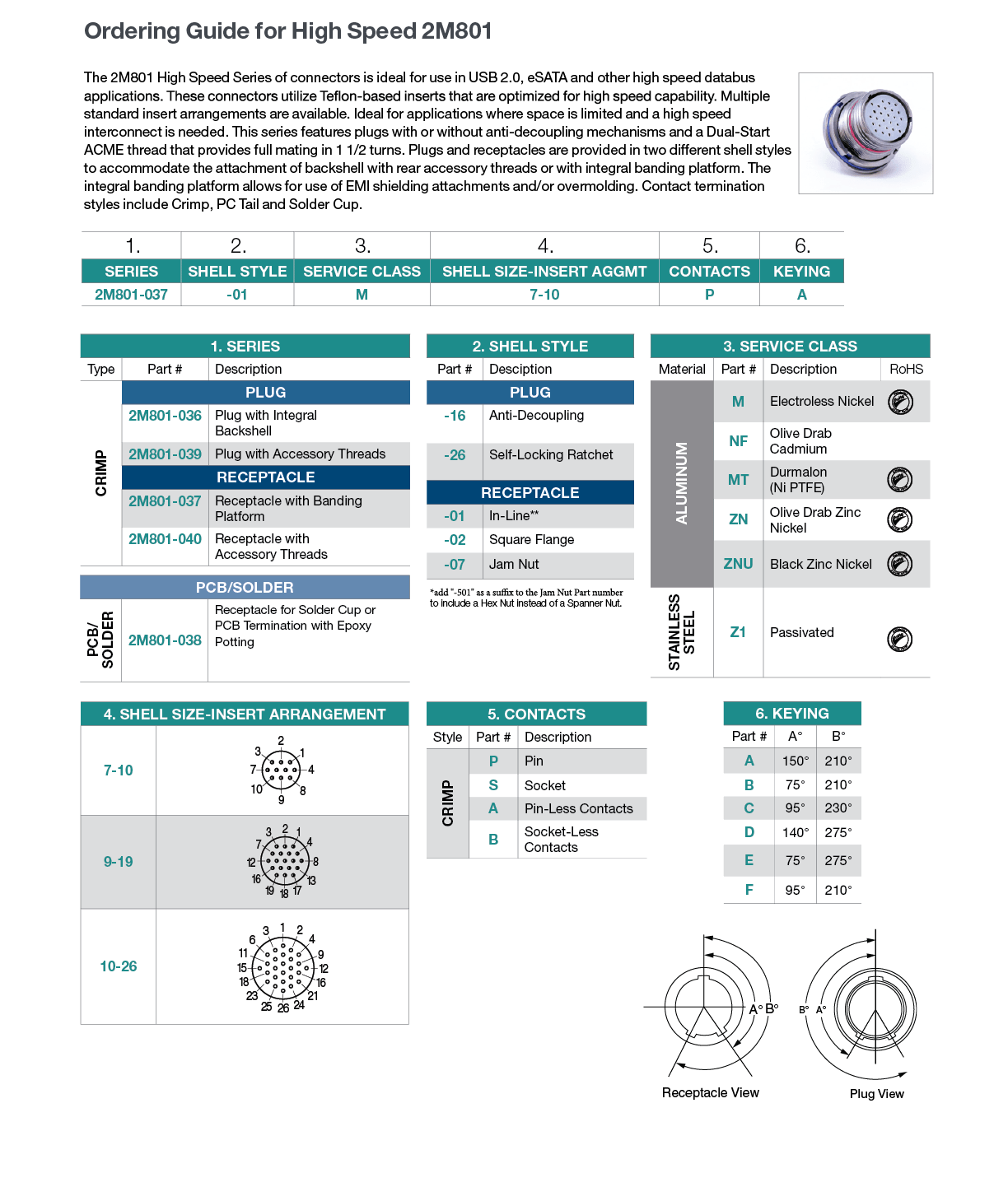
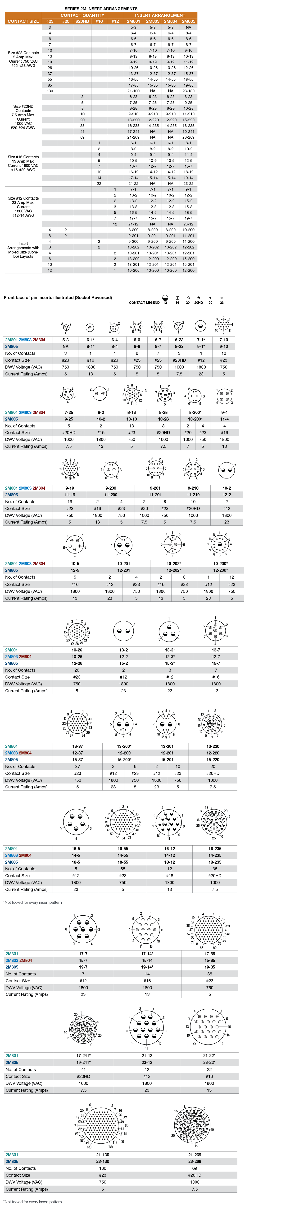
2M801 is generally considered a legacy series. Its successor, the 2M805 series, has a number of important improvements, including a triple-start thread (which reduces the number of turns it takes to fully mate the connectors) and an EMI band (which increases shell-to-shell conductivity and greatly improves signal shielding). You should choose 2M801 if you’re looking to maintain compatibility or interoperability with existing technology or cables.


Weight :
| 2M805 | D38999 | D38999 Aluminum | D38999 Composite | |||||
| Layout | Number of Contacts | Weight | Layout | Number of Contacts | Weight | % Weight Savings | Weight | % Weight Savings |
| 8-7 | 7 #23 | 13.4 | 9-35 | 6 #20 | 26.3 | 49% | 19.9 | 33% |
| 10-13 | 13 #23 | 23.0 | 11-35 | 13 #22D | 35.7 | 36% | 26.8 | 14% |
| 11-19 | 19 #23 | 26.4 | 13-35 | 19 #22D | 50.7 | 48% | 38.5 | 31% |
| 12-26 | 26 #23 | 29.4 | 17-26 | 26 #20 | 58.5 | 50% | 62.6 | 53% |
| 15-37 | 37 #23 | 42.7 | 15-35 | 37 #22D | 72.1 | 41% | 57.4 | 26% |
| 18-55 | 55 #23 | 59.6 | 17-35 | 55 #22D | 81.6 | 27% | 65.6 | 9% |
| 19-85 | 85 #23 | 59.8 | 21-35 | 85 #22D | 119.7 | 50% | 99.1 | 40% |
| 23-130 | 130 #23 | 85.5 | 25-35 | 128 #22D | 159.3 | 46% | 136.6 | 37% |
Size :
| 2M805 | D38999 | Maximum Plug Diameter | Maximum Jam Nut Receptacle Diameter | ||||||||
| Layout | Layout | 2M805 | D38999 | % Reduction | 2M805 | D38999 | % Reduction | ||||
| in | mm | in | mm | in | mm | in | mm | ||||
| 8-7 | 9-35 | .707 | 17.96 | .859 | 21.81 | 17% | .775 | 19.69 | 1.201 | 30.51 | 35% |
| 10-13 | 11-35 | .804 | 20.42 | .969 | 24.61 | 18% | .895 | 22.73 | 1.386 | 30.50 | 35% |
| 11-19 | 13-35 | .933 | 23.70 | 1.141 | 28.98 | 20% | .960 | 24.38 | 1.512 | 38.40 | 36% |
| 12-26 | 17-26 | .999 | 25.37 | 1.391 | 35.33 | 29% | 1.075 | 27.31 | 1.764 | 44.81 | 39% |
| 15-37 | 15-35 | 1.113 | 28.27 | 1.266 | 32.16 | 13% | 1.218 | 30.86 | 1.638 | 41.61 | 26% |
| 18-55 | 17-35 | 1.308 | 33.02 | 1.391 | 35.33 | 7% | 1.404 | 35.66 | 1.764 | 44.81 | 20% |
| 19-85 | 21-35 | 1.328 | 33.73 | 1.625 | 41.27 | 19% | 1.465 | 37.21 | 2.075 | 52.71 | 29% |
| 23-130 | 25-35 | 1.577 | 40.06 | 1.875 | 47.63 | 16% | 1.720 | 43.69 | 2.323 | 59.00 | 26% |
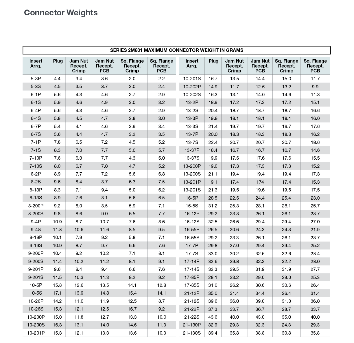
Weight :
| 2M801 | D38999 | D38999 Aluminum | D38999 Composite | |||||
| Layout | Number of Contacts | Weight | Layout | Number of Contacts | Weight | % Weight Savings | Weight | % Weight Savings |
| 5-3 | 3 | 7.9 | 9-98 | 3 | 25.3 | 69% | 19.9 | 60% |
| 6-7 | 7 | 9.8 | 9-35 | 6 | 26.3 | 63% | 19.9 | 51% |
| 9-19 | 19 | 18.8 | 13-35 | 22 | 50.7 | 63% | 38.5 | 51% |
| 13-37 | 37 | 36.0 | 15-35 | 37 | 72.1 | 50% | 57.4 | 37% |
| 16-55 | 55 | 49.8 | 17-35 | 55 | 81.6 | 39% | 65.6 | 24% |
| 17-85 | 85 | 54.3 | 21-35 | 79 | 119.7 | 55% | 99.1 | 45% |
| 21-130 | 130 | 68.7 | 25-35 | 128 | 159.3 | 57% | 136.6 | 50% |
Note: Weights shown include contacts and represent a mated pair of plug and jam nut receptacle. Weights are in grams.
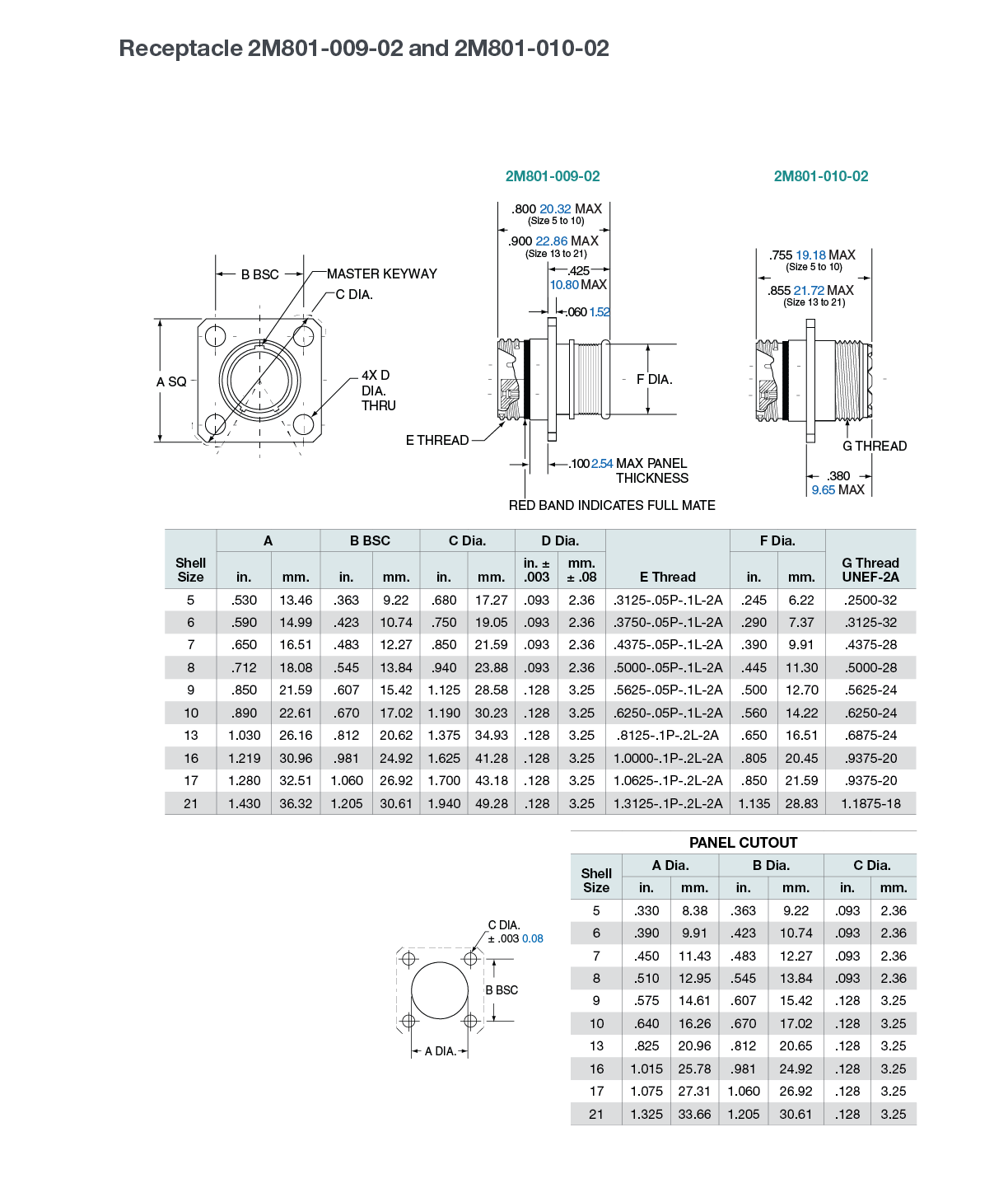
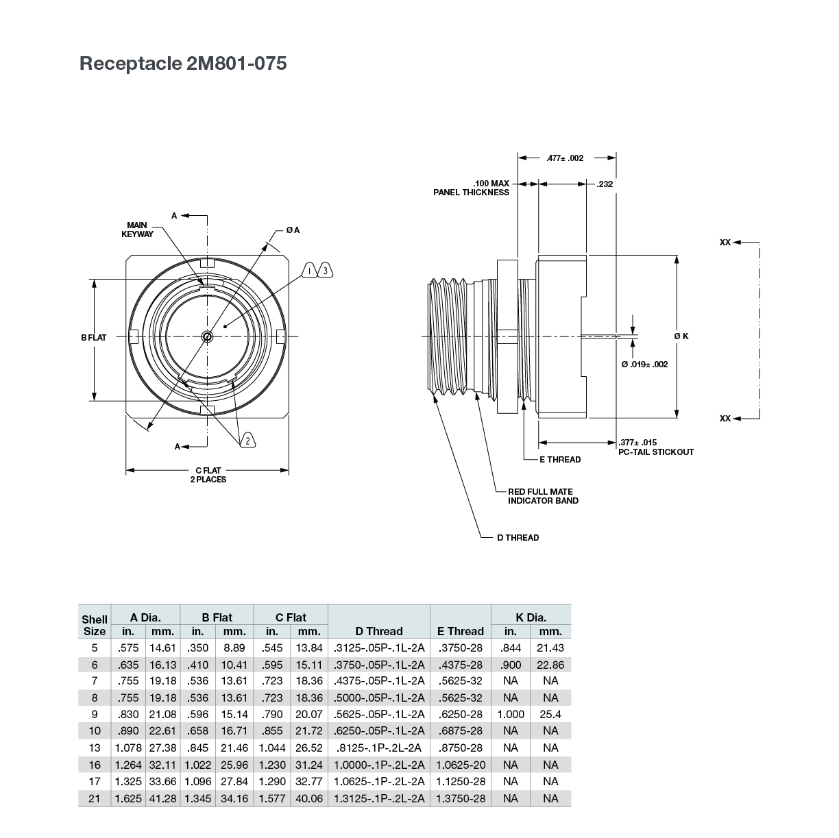
Size :
| 2M801 | D38999 | Maximum Plug Diameter | Maximum Jam Nut Receptacle Diameter | ||||||||
| Layout | Layout | 2M801 | D38999 | % Reduction | 2M801 | D38999 | % Reduction | ||||
| in | mm | in | mm | in | mm | in | mm | ||||
| 5-3 | 9-98 | .540 | 13.72 | .859 | 21.82 | 37% | .575 | 14.61 | 1.204 | 30.58 | 52% |
| 6-7 | 9-35 | .600 | 15.24 | .859 | 21.82 | 30% | .635 | 16.13 | 1.204 | 30.58 | 47% |
| 9-19 | 13-35 | .810 | 20.57 | 1.156 | 29.36 | 30% | .830 | 21.08 | 1.516 | 38.51 | 45% |
| 13-37 | 15-35 | 1.050 | 26.67 | 1.281 | 32.54 | 18% | 1.078 | 27.38 | 1.641 | 41.68 | 34% |
| 16-55 | 17-35 | 1.240 | 31.50 | 1.406 | 35.71 | 12% | 1.264 | 32.11 | 1.766 | 44.86 | 28% |
| 17-85 | 21-35 | 1.300 | 33.02 | 1.641 | 41.68 | 21% | 1.325 | 33.66 | 2.078 | 52.78 | 36% |
| 21-130 | 25-35 | 1.550 | 39.37 | 1.890 | 48.01 | 18% | 1.625 | 41.28 | 2.323 | 59.00 | 30% |
Note: Weights shown include contacts and represent a mated pair of plug and jam nut receptacle. Weights are in grams.
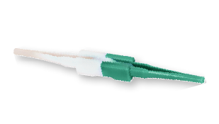
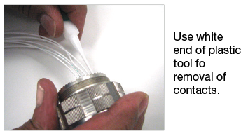
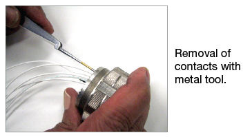
Note: All plastic tools are double-ended. The colored side is the insertion tool and the white side is the removal tool.